FALLINGWATER CANOPY
This report was part of my final project for the course Applied Finite Elements.
Project Summary:
Creo Simulate FEA study of the canopy at Frank Lloyd Wright’s Fallingwater house, using gravitational and distributed snow loads to assess its performance against structural requirements. The canopy was simulated as an entire assembly and as a segment to investigate how the structure gains additional rigidity from its overall elliptical shape to safely cantilever such a large concrete slab.
Model Inspiration:
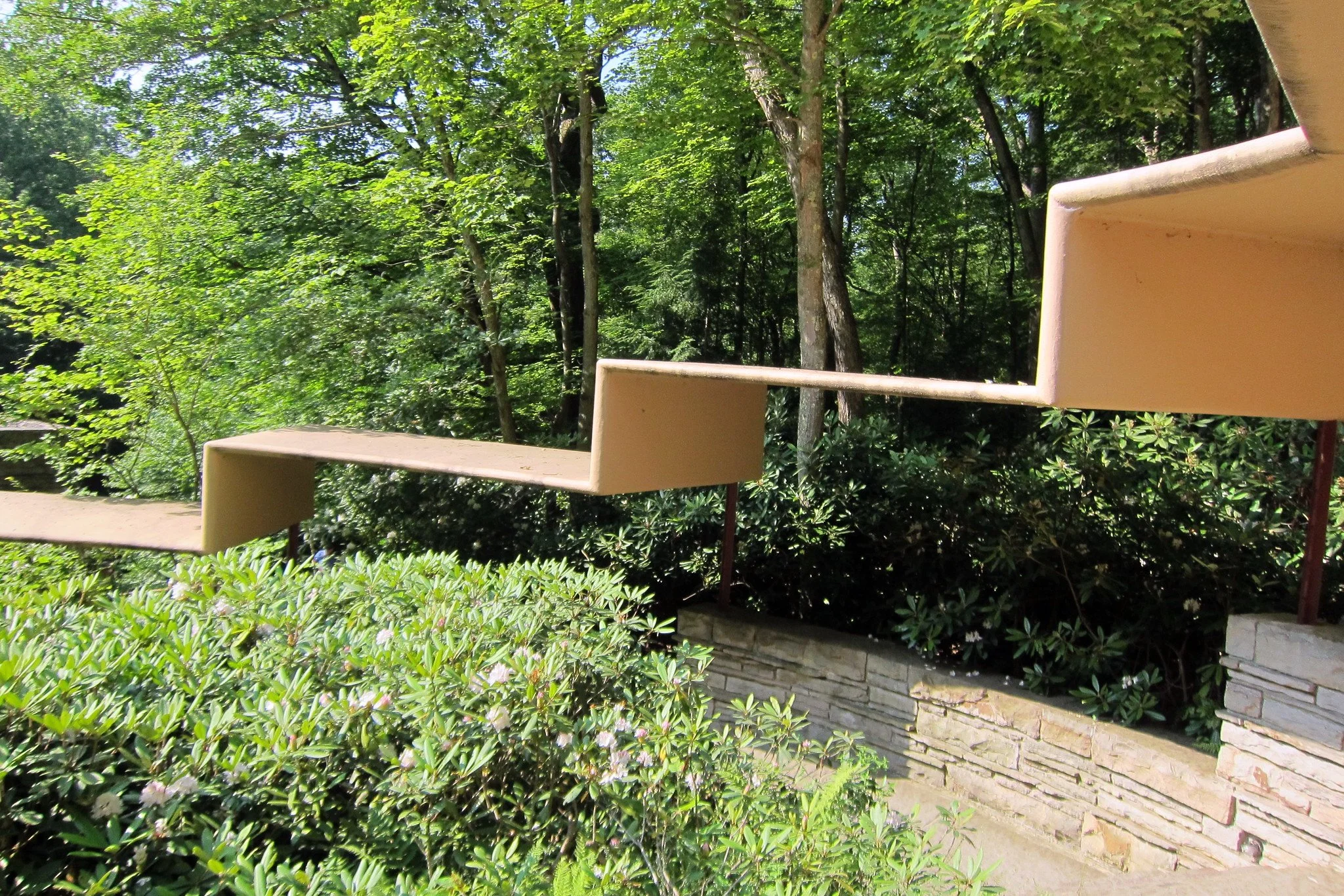
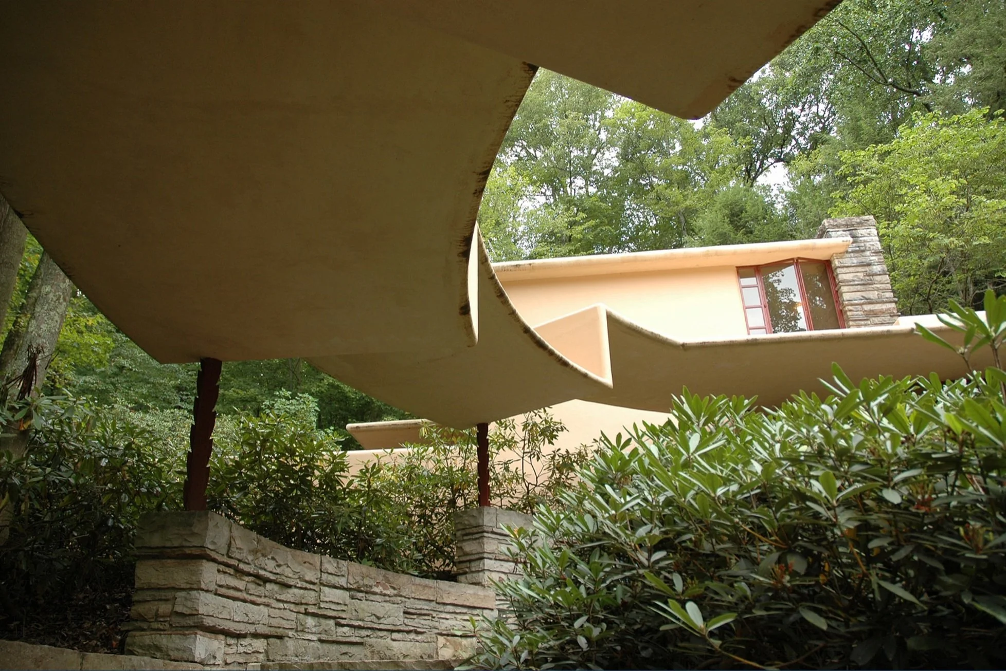
The canopy at Fallingwater, a home designed by Frank Lloyd Wright, is the largest continuous cantilevered structure in the building. It covers the open walkway from the guest house to the main residence.
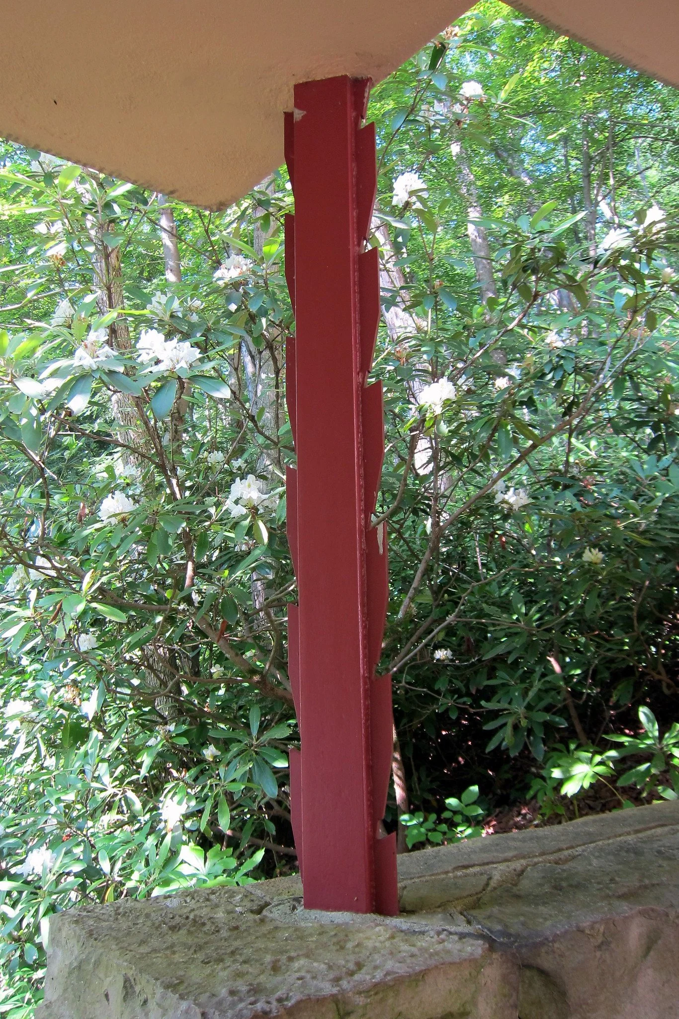
The canopy was built in 1939 and consists of a series of steel columns, constructed from welded steel angles, supporting a reinforced concrete slab.
The slab, made up of folded planes, is cantilevered from the thin columns but gains additional rigidity from its overall elliptical shape which can best be seen when viewing the structure aerially.
CAD Model:
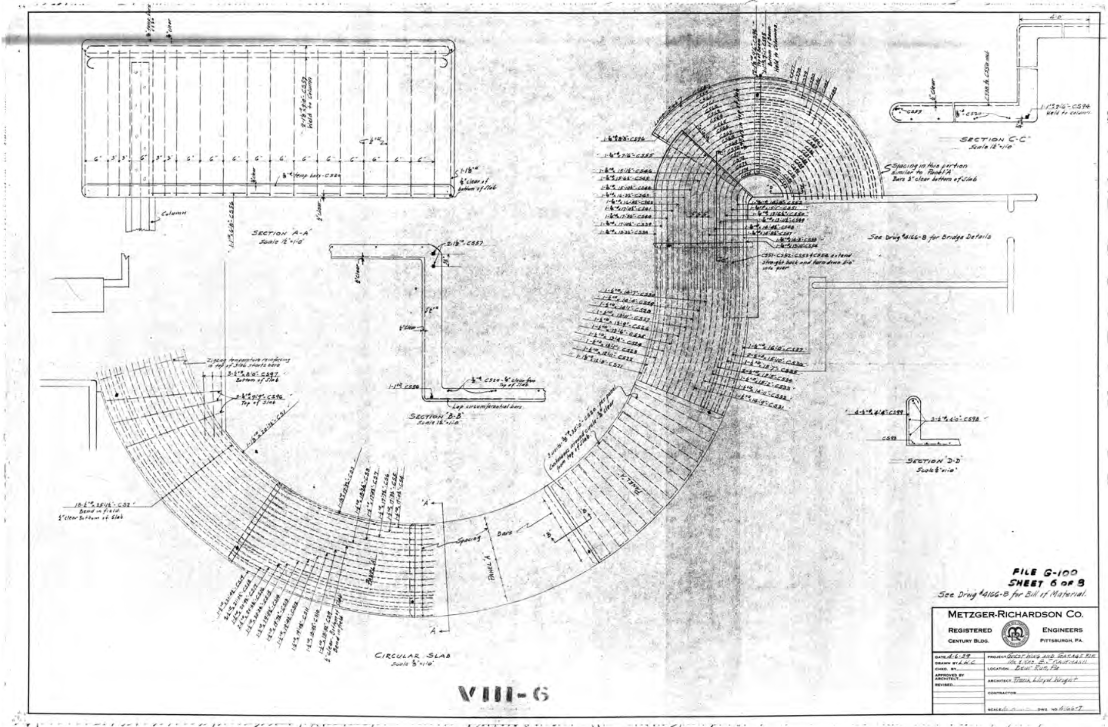
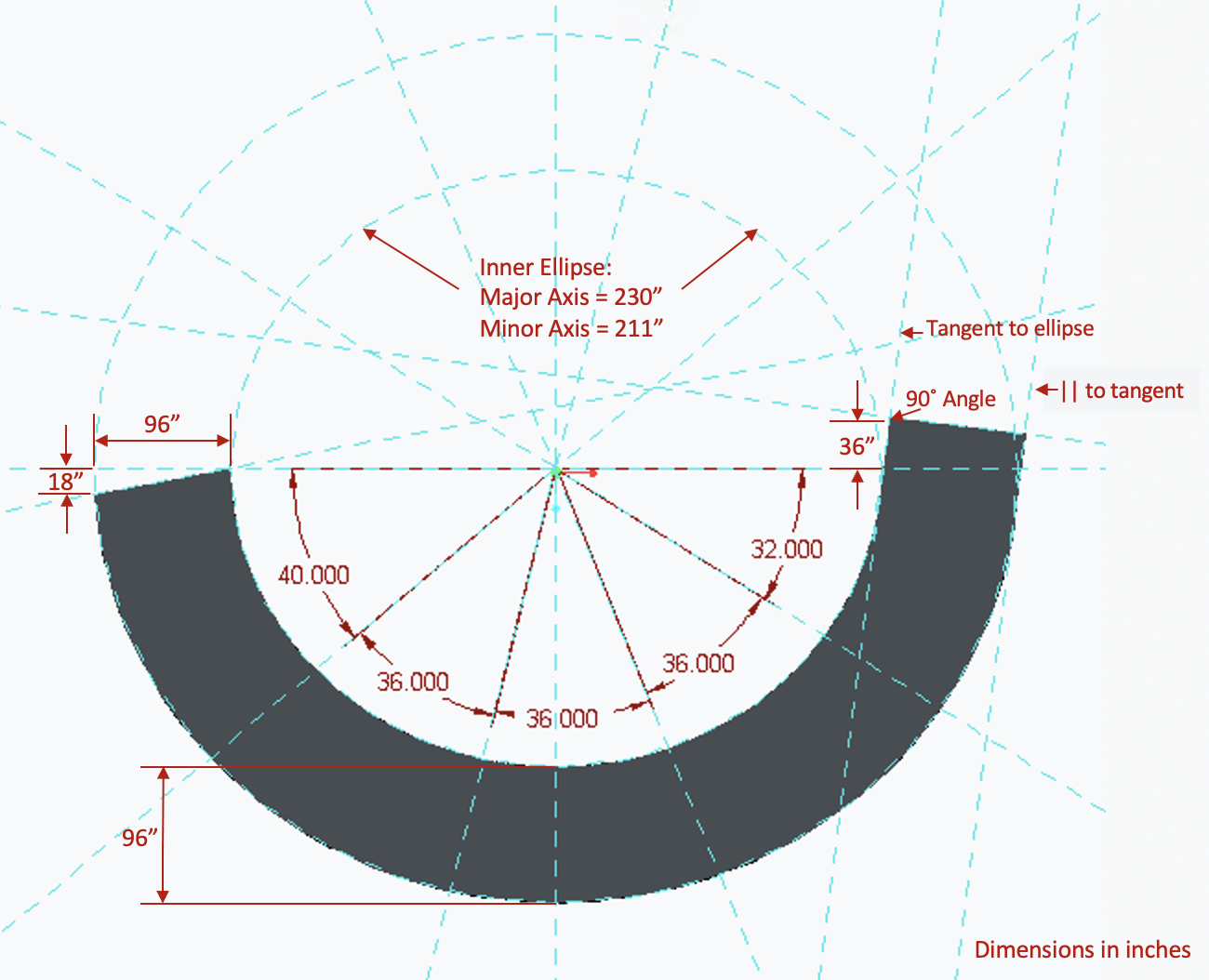
The model geometry was derived from scans of Frank Lloyd Wright’s original plans and made in Creo. Lengthwise and width-wise square steel bars reinforce the 8-foot wide concrete down the path. Two welded steel angles make up the columns which are each 3.5 feet tall. All components were bonded.
The bases of each column were modeled as fixed – in real life, the bases meet a stone wall into which the columns are cemented.
Aerial view of the canopy with dimensions in inches
Structural Requirements:
Concrete Slab:
Deflection is limited to 1.4 inches [Immediate elastic deflection limit of concrete slab is equal to L/180 per ACI 318 for roof members, where L is the length of the unsupported slab between columns]
Must not yield with safety factor of 1.5 [IS 45:2000]
Steel:
Must not yield with safety factor of 23/12 [AISC for columns with end restraint and bending]
Analysis:
Five (5) analyses were run on the model, with the following conditions:
Gravity loads only, low-carbon steel and standard concrete, coarse mesh (max. size 10 in)
Repeat Analysis 1, adding a distributed snow load @ 40 PSF [per Section 1608 of the International Building code].
Repeat Analysis 1, using high-carbon steel to reduce column stresses.
Repeat Analysis 3 with refined mesh to see if stresses and displacement are affected.
Repeat Analysis 4 with a partial assembly of the canopy.
Results:
Replacing the low-carbon steel with a high-carbon steel tripled the columns’ yield strength while keeping the magnitude of stresses mostly the same, allowing the columns to meet the structural requirements. The coarse mesh (max. element size 10 inches) used to reduce runtime was found to have consistent results with a much finer mesh (max. element size 1 inch) based on a repeated simulation.
In all analyses, the concrete slab was found to fail the stress requirements. Certain corners where columns met the slab created singularities, and further work is needed to refine the model to reduce unrealistic stress concentrations. However, excluding these areas, the slab still failed under gravitational loads, exceeding the allowable stress by a factor of 3-5x on average. If further analyses had been possible, I would recommend the concrete be simulated with different tensile properties. Some assumptions about the geometry including the choice not to simulate the guest house where the canopy connects may contribute to differences in the simulated vs. real structures. Deflection of the slab was generally within acceptable limits.
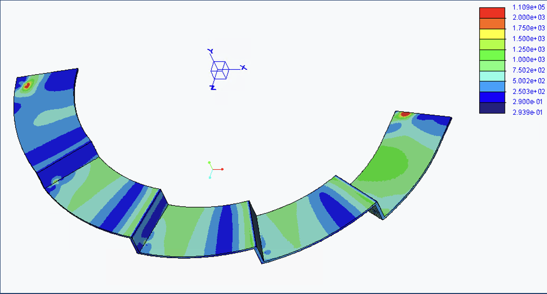
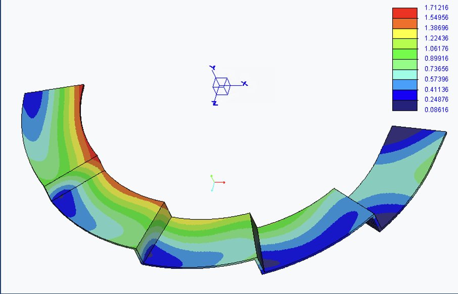
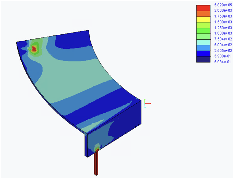
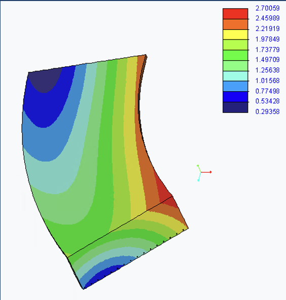
It was shown that when a piece of the canopy was simulated in isolation, the stresses increased at the edges and middle of the slab by ~100 psi [Fig. 1 and 2]. This demonstrates that the structure is gaining needed strength from its overall shape that it does not have when segmented. The maximum displacement of the slab [Fig. 3 and 4] and the yielding in the columns was also much greater for the segmented structure, supporting the conclusion that the overall structure resists bending and works as a cantilever in part due to its elliptical shape.
Figure 1. Rescaled Von Mises Stress (psi) on Full Concrete Slab [Gravitational Loading, High-Carbon Steel]
Figure 3. Displacement (in) on Full Concrete Slab [Gravitational Loading, High-Carbon Steel]
Figure 2. Rescaled Von Mises Stress (psi) on Partial Concrete Slab [Gravitational Loading, High-Carbon Steel]
Figure 4. Displacement (in) on Partial Concrete Slab [Gravitational Loading, High-Carbon Steel]
