Reverse Engineering Design Analysis of the Ford 8N Tractor Starter Motor
This report was part of my final project for the course Reverse Engineering and Diagnostics.
Project Summary:
The objective of this project was to investigate the design of the Ford 8N tractor electric starter motor, including component materials, manufacturing processes, and functions. A specific analysis of the the pinion and ring gears was conducted to determine the suitability of their design for the application.
The analysis demonstrated that the gears were suitably designed as the stresses developed were beneath the failure criteria. However, the analysis excluded the contribution of some loads which could not be derived. Considering all possible loading, it is reasonable that these gears are occasionally replaced on 8N tractors due to wear. Modern starter motors have opted for a pre-engaged starting mechanism to eliminate sources of wear on the gear teeth present in the 8N starter.
Starter Motor Background:
Although internal combustion engines rely on a feedback system while operating, with each cycle powering the next, the first few engine strokes require energy input to turn the motor over. In early motors, this was achieved using a hand crank. The starter motor revolutionized the automotive industry by eliminating the risk of hand crank related accidents and offering a fast, convenient alternative to start an engine.
Figure 1. Starter Motor Exploded View
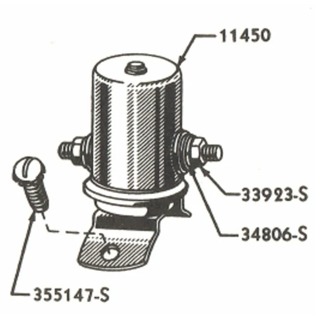
Figure 1 shows the entire starter motor subassembly. The components of the Bendix drive subassembly are shown at the bottom (P/N 11350) and the starter solenoid is located in the top left (P/N 11450).
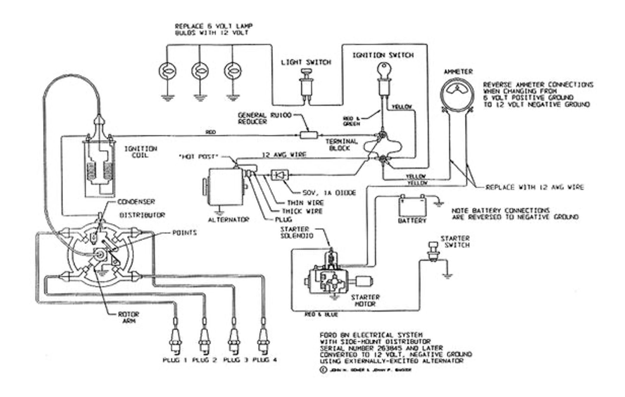
Figure 2. Ford 8N Tractor Wiring Diagram
Figure 2 shows the wiring diagram for the 8N tractor. Importantly, it depicts the connection between the starter motor, starter solenoid, battery, and starter switch. Discussed further in the analysis, the starter switch provides a low current from the battery to the starter solenoid, which is an electromagnetic actuator that in turn closes two high-current contacts. This connection ultimately provides power to the motor and allows it to run.
Materials and Manufacturing:
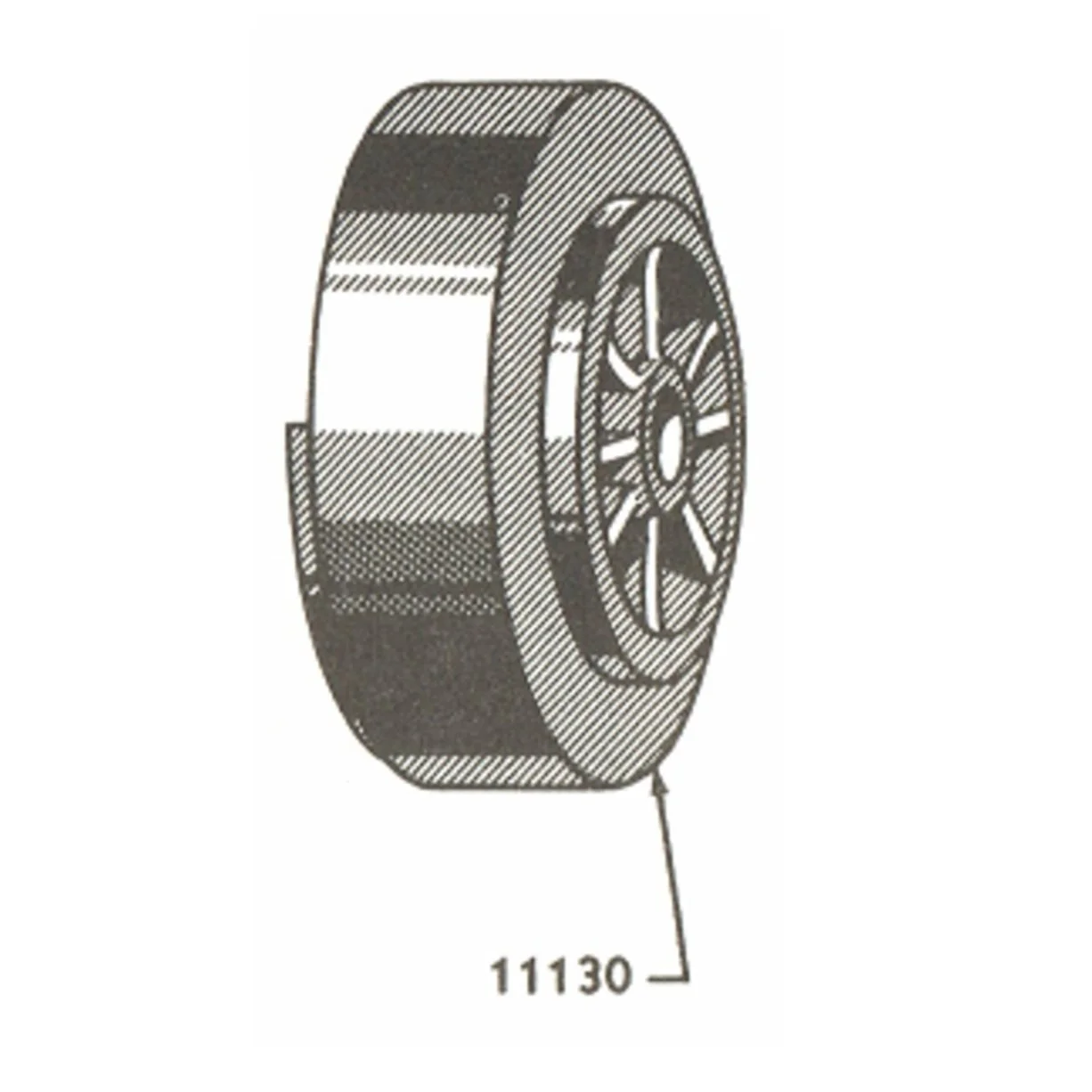
Motor End Cap
The end cap shown and its opposing counterpart are constructed from aluminum. This is suitable for a part that undergoes small loads – primarily bolt tightening forces, vibrational effects, and small loads from the spinning armature shaft which are reduced by a concentric bearing.
The end caps are likely cast aluminum due to surface appearance and lack of tight tolerance requirements. The critical features are threaded holes connecting to bolts in the assembly and a central hold containing the bearing which are machined after casting.
The main function of these parts is simply to hold the motor assembly together.
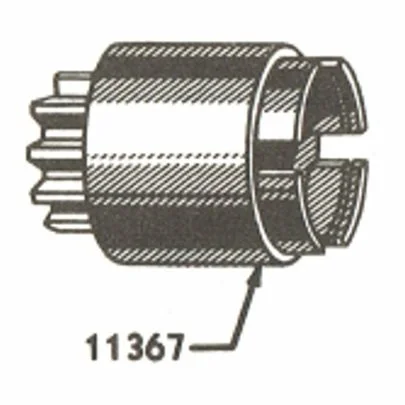
Pinion Gear
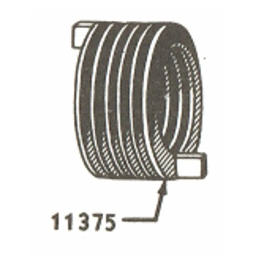
Bendix Spring
The pinion gear is constructed from a hardened steel due to larger loads and stresses applied to the gear teeth from engaging with the flywheel.
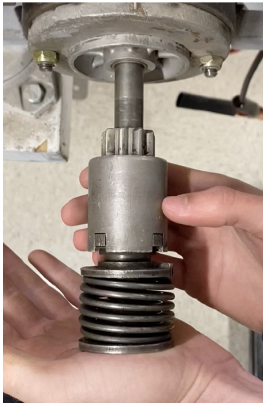
The 8N starter motor uses a Bendix drive engagement system and also relies on the pinion assembly’s inertia to resist motion when the motor begins turning. This is what causes the pinion to advance along the threaded shaft and compress the Bendix spring.
The exact composition of the gear was not possible to determine, but it is reasonable the manufacturer would use a plain carbon or alloy steel that is heat treated for toughness since the component is prone to wear. Cast iron may also be used due to ease of machinability and resistance to wear.
The pinion gear is likely constructed from a series of hobbing and milling operations to ensure tight tolerances while remaining relatively inexpensive.
Starter Solenoid
The starter solenoid is an example of materials selection based on electrical or magnetic requirements rather than applied loads. The solenoid requires a ferrous (iron) core to be actuated.
The armature also contains a soft iron core. High current terminals in the solenoid assembly, the solenoid itself, and the armature windings are made of copper and sometimes aluminum for electrical efficiency due to high electrical conductivities.
Starter Solenoid Function:
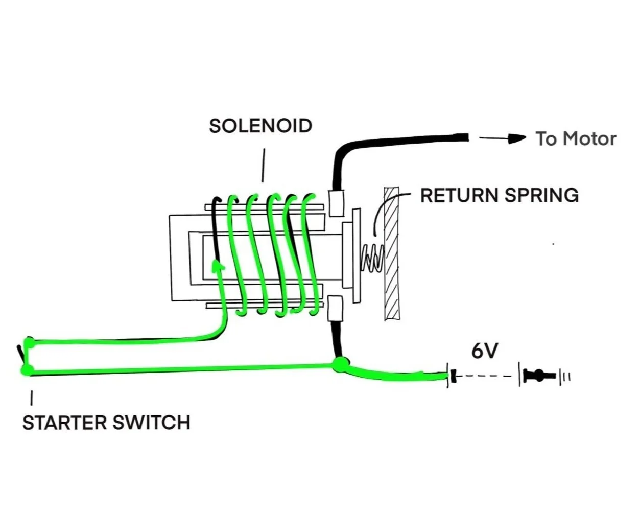
1. Starter Switch Closed
To begin, the starter switch is pressed and current flows from the battery through the solenoid.
2. Magnetic Field Induced
The current draw is relatively small, around 50 Amps. However, it is enough current to induce a magnetic field, shown by the blue field lines.
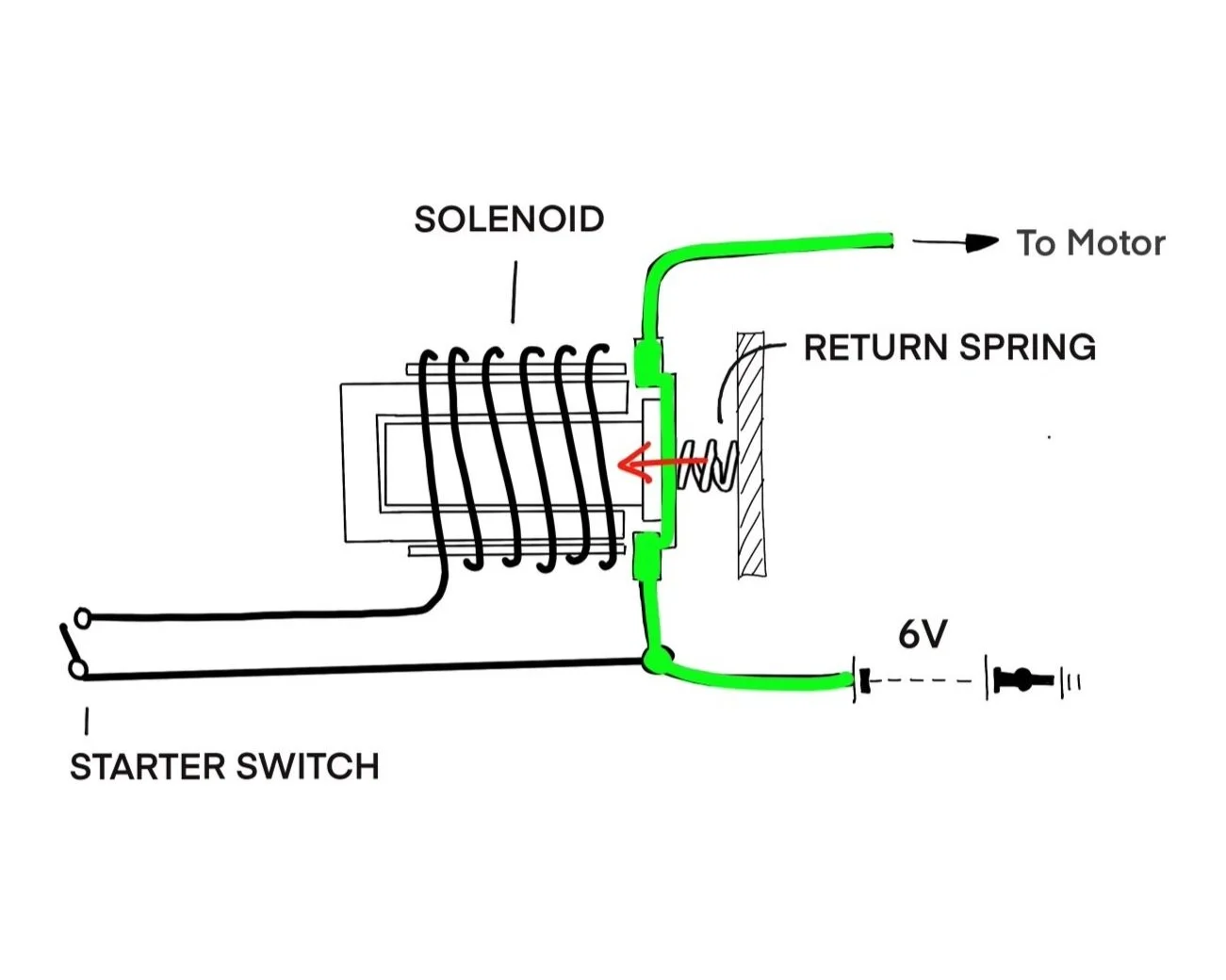
3. Motor Contact Closed
The magnetic field provides an attractive force that causes the ferrous core plunger to move inside the solenoid, closing the high current copper contacts and allowing current to flow to the motor. The ground path for the solenoid (the “pull in” winding) has been cut off, so there is no current flow.
The series of figures above show a simplified diagram of the starter solenoid in use. Not pictured is the secondary, “hold in” winding, which still has current flow, and is responsible for holding the plunger in the closed position while the starter motor runs.
The starter solenoid is a cleverly designed component that is a safe and inexpensive alternative to having a direct switch connecting the motor to the battery. When running, the starter motor draws 150 to 200 Amps, which would be too much for a simple switch to handle. Large cables running a long length would be necessary to carry this amount of current without loss creating a considerable expense. Solenoids are a cheap option that eliminates the need for these cables and prevents a potential fire hazard by efficiently controlling a large amount of current while drawing only a fraction of the amount.
Bendix Drive Analysis:
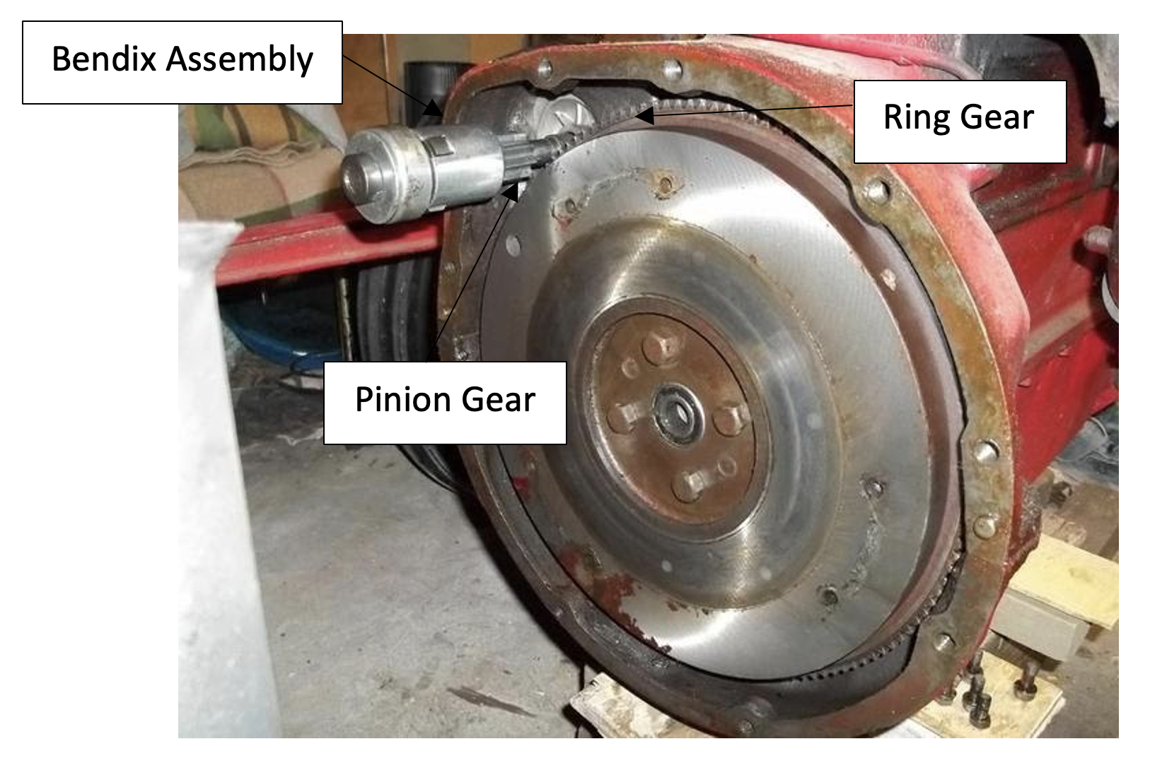
The Bendix drive is the mechanism used in the N-series starter motors, and many older starters, to engage and disengage the pinion gear of the motor assembly with the ring gear on the engine flywheel.
Figure 3. Pinion gear in disengaged position
Figure 4. Pinion gear in engaged position
The Bendix drive places the pinion gear assembly on a helically threaded drive shaft. Due to some initial inertia, the pinion assembly does not immediately begin rotating at the same speed as the motor, and instead advances along the shaft to the “engaged” position (Fig. 4).
When engaged, the Bendix spring is fully compressed which moves the pinion assembly forward an additional 0.5 inches. The the pinion gear meshes with the ring gear (not shown), and begins turning over the flywheel. Eventually, once the flywheel and crankshaft are turned up to speed, the cylinders will be firing and the engine will begin operating on its own power. At this point the rotational velocity of the flywheel will begin to exceed that of the pinion, which will throw the pinion gear out of mesh and release the compressive force on the Bendix spring.
Gear Analysis:
The two primary failure modes for gears are 1) tooth breakage due to bending stress and 2) surface pitting and wear from contact stress.
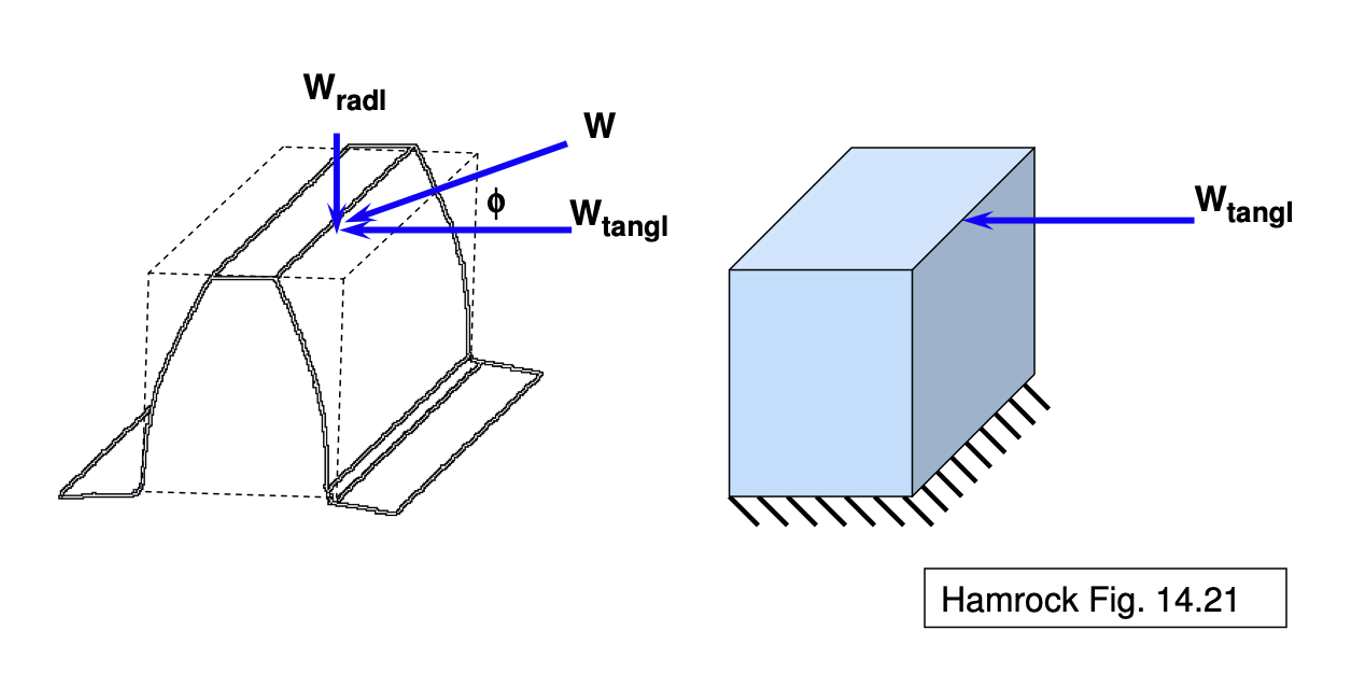
Figure 5. Gear Tooth Bending Stress
Figure 5 shows an approximation of a gear tooth as a cantilever beam. Using the Lewis Bending Stress equation, we can develop an expression for the stress in the tooth caused by the tangential load (Wtangl).
Image Source: http://www.faculty.fairfield.edu/wdornfeld/ME312/ToothLoads04.pdf
Analysis:
The tangential load was derived from the ring gear torque required bring the flywheel up to speed (200 rpm) in 500ms. The corresponding input pinion gear torque was derived from the gear ratio. After deriving the tangential load and gear velocity at the pitch diameter, the bending stresses were calculated from the gear measurements.
Results:
The bending stress developed in the pinion gear as a result of bringing the flywheel up to speed was found to be approximately 9,600 psi and in the ring gear approximately 15,000 psi. These were both less than 1/3 of the ultimate tensile strength (UTS) of the material, assumed to be a hardened steel (UTS 600 MPa or 87,000 psi). Therefore, the gear will not fail due to bending stress under the considered loading.
Limitations:
The analysis excluded the torque required to turn over the crankshaft assembly and turn the engine pistons against the internal cylinder pressures. The inclusion of these loads would likely have the strongest effect on the stresses in the ring gear as the width of the teeth is much smaller.
Figure 6. Gear Teeth Contact Stress
Contact stresses in the gears can be determined using a Hertzian Contact Pressure approximation, in which the gear teeth are modeled as a pair of cylinders (shown in dashed lines in Figure 8) in line contact.
Image Source: http://www.faculty.fairfield.edu/wdornfeld/ME312/ToothLoads04.pdf
Analysis:
The contact stress between the pinion and ring gears caused by bringing the flywheel up to speed was derived from the tangential load. Unidirectional loading, 10^7 stress cycles, and 99% reliability were assumed.
Results:
Given the assumptions, the maximum allowable contact stress for hardened steel was found to be 150-250 ksi. The contact stress due to the tangential load of turning the flywheel from rest to 200rpm in 500ms was found to be approximately 93 ksi. This is below the maximum allowable stress, therefore the gear will not fail due to contact stress under the considered loading.
Limitations:
The contact stress does not account for the primary source of tooth wear associated with the Bendix. The main drawback of Bendix-type starters is the fact that the ring gear is already spinning at a relatively high speed when it is forced to engage with the stationary flywheel. They are rarely perfectly aligned when they meet so this causes some initial grinding of gear teeth before they ultimately mesh.

